A METHOD TO DETERMINE THE POWER OF A TRANSFORMER
What is the power ?
INTRODUCTION
Finding an affordable high voltage transformer for supplying an HF amplifier is increasingly becoming a problem. People are now asking for a fortune for a new one! Affordable sometimes it still works at a flea market or an older amateur is still interested.
Het vinden van een betaalbare hoogspanning transformator voor het voeden van een HF versterker begint steeds meer een probleem te worden. Voor een nieuw exemplaar vraagt men inmiddels een fortuin! Betaalbaar lukt het soms nog op een vlooienmarkt of heeft een oudere zendamateur nog iets liggen.
POWER UNKNOWN TRANSFORMER
If, at first glance, a suitable transformer has been hit, does the label still contain the necessary information? Without this data, the power remains an unknown factor.
There are all kinds of ways to determine whether a transformer is suitable for a certain capacity. You can determine the weight or measure the lamination core etc. Over the years the construction of transformers has changed, so that the old measuring methods no longer apply as well. In the last century, as a starting amateur amateur, I got the following (reasonable) method of estimating the power from an oldtimer: "Measure the DC resistance of the secondary winding". The procedure is as follows:
Als men op het eerste gezicht een passende transformator op de kop heeft getikt, staat dan ergens nog de nodige informatie op een etiket? Zonder deze gegevens blijft het vermogen een onbekende factor.
 Suppose 2000 Volt is the no-load secondary voltage; Usec = 2000 VAC
At full load the secondary voltage may collapse 5% (= U × 0.95)
Uload = 0.95 × 2000 = 1900 VAC
Measure the DC resistance (Rsec) of the secondary winding.
Suppose that Rsec = 100 Ohm.
The maximum current is then:
Imax = (Usec - Uload) ÷ Rsec = (2000 - 1900) ÷ 100 = 1 Amp
Then it is a:
Uload × Imax = 1900 × 1 = 1900 Watt transformator (1.9 kW trafo).
That is the power with continuous load!
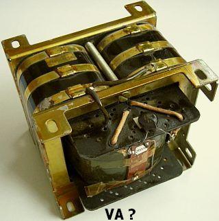
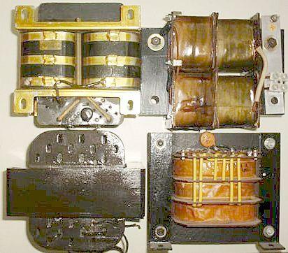
It is not a infallible method, but in practice I have found that it is still usable. For example it turned out to work with (fig ») these four different transformers.
INTERMITTENT (SSB) POWER
Because SSB is an intermittent transmission, a transformer is only fully loaded at the peaks (PEP) of the modulation. The average power is considerably less than with a continuous load.
That is why with SSB you can double the power of a transformer.
The above fictional 1900 W type is for SSB a:
2 × 1900 W = 3800 Watt transformator.
With an HF amplifier you can assume a 50% efficiency.
Then the SSB output is SSBoutput = 0.5 × 3900 W = 1900 Watt PEP.
The conclusion is then:
With SSB a 1900 W transformer is suitable for 1900 W PEP ICAS ouput.
ICAS = Intermittent Commercial and Amateur Service.
POWER WITH RECTIFICATION
With rectification, the no-load DC voltage of the 2000 VAC transformer is:
1.41 × 2000 VAC = 2820 VDC.
At full load (CW, key down) the voltage usually drops to 2000 VDC.
With SSB, the average voltage is about 2400 VDC.
The collapse is due to the internal resistance of the transformer and the resistance of other components. Because the average voltage with SSB is higher than with a carrier wave (CW), the PEP power is higher than with a continuous transmitted signal.
IN BRIEF
With a transformer, the loaded rectified DC voltage is in value equal to the unloaded alternating voltage:
VDCload = VAC.
With SSB a transformer can deliver twice the power according to the specification.
Pssb = 2 × Pspec
DOUBLING
A high voltage can be obtained economically by doubling or quadrupling («fig). There is a relatively negative written article about such a method. Apparently such an author has never tried something like this or has applied components that do not belong in the circuit. If capacititances of sufficient values are used, then a decent supply of a higher voltage can be made.
With this method, it must be borne in mind that the maximum current to be supplied after doubling or quadruple must be divided by 2 or by 4, so as not to exceed the power of the transformer.
![]()
![]()